01
An integrated treatment process
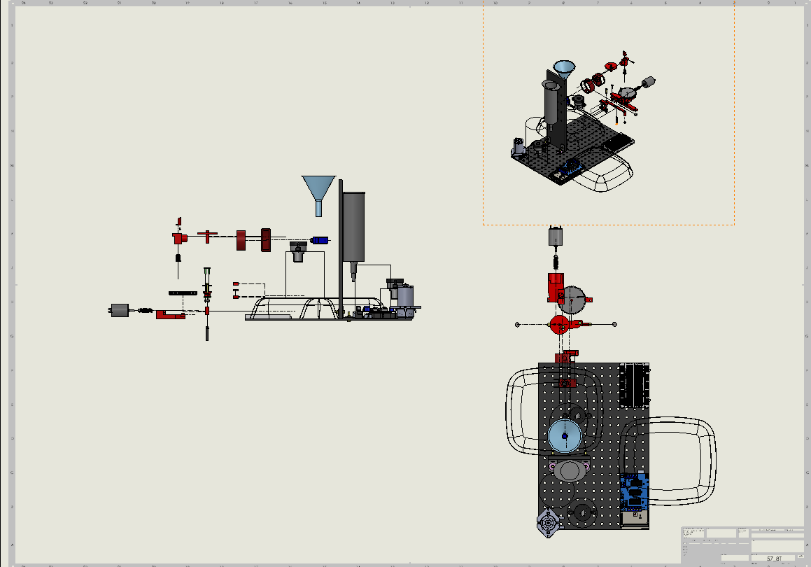
Our team designed, built, and tested a small automated water pre-treatment prototype for the course scenario of Awesome, Nunavut. The process added an alum mixture to water containing bentonite clay, mixed and settled the suspension, then transferred water through a sand filter.
The main engineering challenge was integrating powder metering, magnetic mixing, fluid transfer, and sensor-based sequencing within a compact assembly. The prototype demonstrated clarification and filtration; it did not establish that the output was safe to drink.
02
My role within the team
Responsibilities were shared across the team. I contributed to mechanical design, prototype fabrication and integration, testing, analysis, and documentation. The assemblies, automated process, and results presented here are shared team accomplishments.
03
Functional requirements
| Requirement | Design consequence |
|---|---|
| Dispense 0.8 ± 0.2 g of alum mixture | Use a repeatable metering cavity and controlled discharge |
| Fit within 204 × 305 mm and 260 mm height | Integrate reservoirs, mechanisms, and electronics compactly |
| Work within a 30,000 mm³ printed-material allowance | Constrain the volume of custom printed components |
| Produce 50 mL of treated water per cycle | Coordinate filling, dosing, mixing, settling, and extraction |
| Operate automatically with accessible reservoirs and protected electronics | Sequence sensors and actuators while accounting for water handling and maintenance |
The listed dose is a requirement, not evidence that every dispense achieved that tolerance. The report identifies powder-delivery reliability as an unresolved issue.
04
System operation
- Start the cycle and fill the coagulation tank using a centrifugal pump; the team checked a 250 mL input volume.
- Rotate the servo-driven metering wheel to release the alum mixture.
- Run the geared magnetic stirrer to distribute the coagulant, then allow clarification.
- Monitor the turbidity-sensor signal and use the selected threshold to permit extraction.
- Transfer water using a peristaltic pump through a syringe-based sand filter into the output reservoir.
Arduino coordinated the sequence. The report describes tests of the start input, pumps, servo, mixer, and sensor threshold, but does not include a usable code listing; the emphasis here is the implemented system behaviour.
05
A rotary powder dispenser
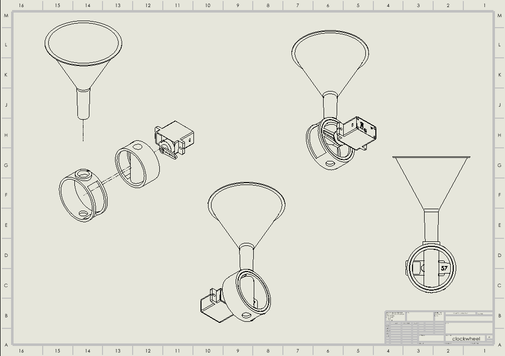
The dispensing mechanism used an inner wheel with a metering cavity inside a stationary outer wheel. After filling, the servo rotated the wheel through 180° to discharge the dose. The solid perimeter blocked the feed opening during rotation to limit continued powder flow.
The design specified a 0.4 mm sliding clearance between the wheels and a friction-fit connection to the servo. Printed alignment and powder behaviour made the mechanism less reliable than the geometric model suggested: the report describes jamming, misalignment, and inconsistent dispensing.
The team proposed revising the clearance and considering vibration to assist powder flow. These were recommendations for a later iteration, not demonstrated fixes.
06
Geared magnetic mixing
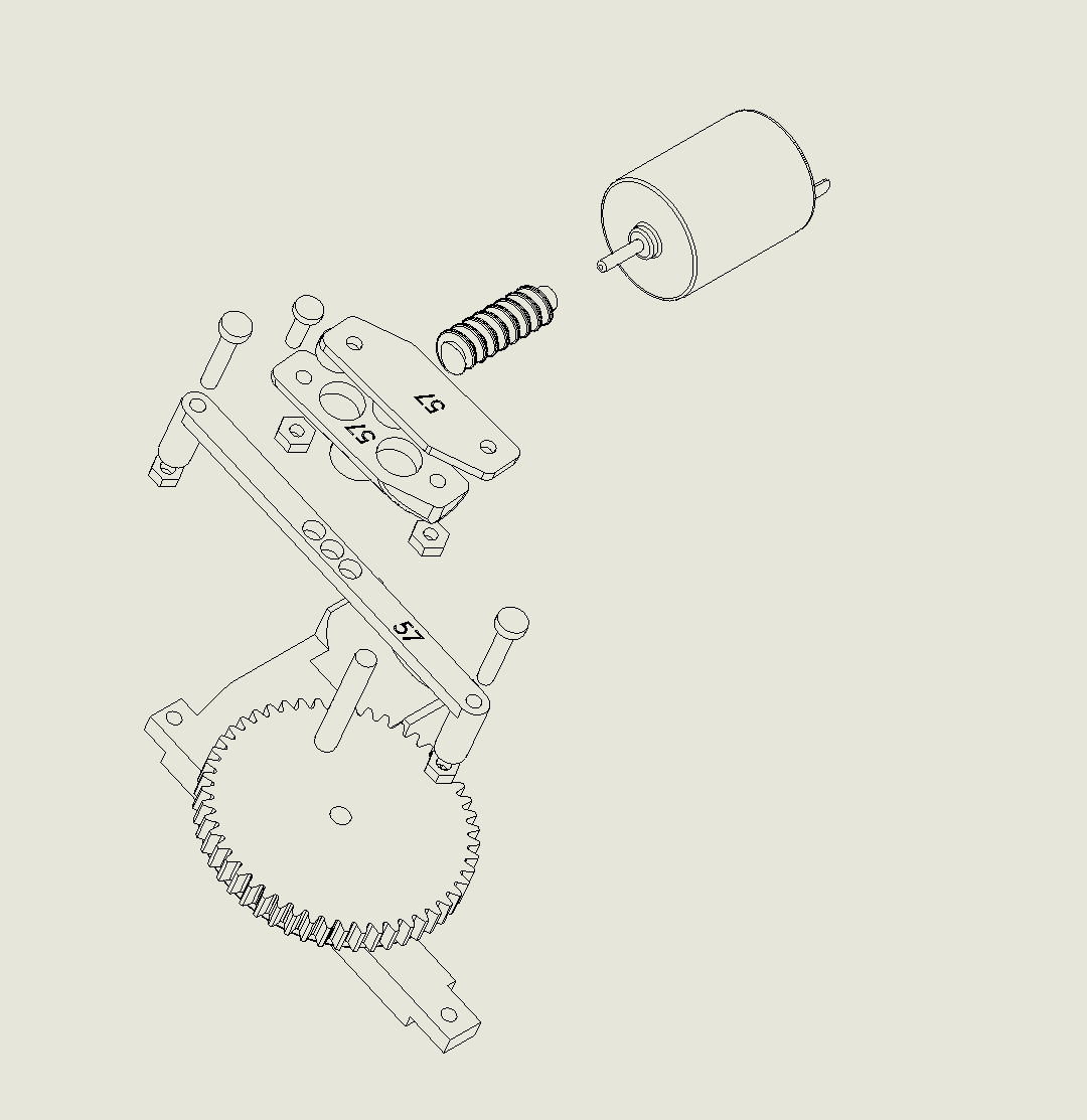
A DC motor drove a worm-and-wheel reduction that rotated magnets coupled to a mixing bar in the tank. The selected design used a nominal 50:1 reduction, with 30:1 and 20:1 alternatives considered if the initial configuration did not perform as expected.
Testing exposed an axial constraint problem: magnetic attraction lifted the mixing-bar guide into the housing, increasing friction and disrupting gear engagement. The report records a temporary remedy, while recommending a more robust guide arrangement and a smaller assembly footprint.
This failure connected magnetic coupling forces, bearing or guide support, gear alignment, and packaging. Adequate motor output alone did not ensure reliable mixing.
07
Integration testing & reported results
| Measure | Reported observation | Interpretation |
|---|---|---|
| Input fill | 250 mL checked during pump testing | Pump-volume verification |
| Output | 50 mL per cycle | Reported prototype throughput |
| Cycle duration | Less than 10 minutes | Reported overall process time |
| Sensor response | Approximately 4.1 V; report also states output within 0.3 V of clean tap water | Electrical comparison, without a supplied calibration curve |
| Automation | Correct sequencing and operation without intervention reported | Demonstrated integration; repeated-cycle reliability not quantified |
The report associates approximately 4.1 V with a turbidity value, but provides no calibration record supporting that conversion. This case study therefore reports the voltage comparison without claiming a verified NTU value, regulatory compliance, or removal of all contaminants.
08
Where the prototype needed improvement
| Subsystem | Issue | Proposed next iteration |
|---|---|---|
| Powder metering | Wheel misalignment, friction, jamming, and inconsistent discharge | Improve guidance and clearance; evaluate vibration and repeat dose-mass trials |
| Magnetic mixer | Guide lift, housing contact, gear slip and wear | Constrain axial movement and verify alignment under magnetic load |
| Packaging | Large mixing assembly complicated support of the tank | Reduce footprint while retaining service access and stiffness |
| Measurement | Sensor-voltage comparison without calibration data | Calibrate the sensor and log repeated tests against reference samples |
The strongest outcome was a working integrated prototype together with specific failure modes that could inform the next design. The full-scale treatment plant discussed in the report was a hypothetical extension; it was not built or validated.
09
Engineering lessons
This project showed why subsystem checks have to be followed by testing the assembled system. Printed fits affected powder delivery, magnetic forces changed the mixer’s alignment, and the sensor location and threshold affected when water was extracted.
A further iteration would prioritize repeatable dosing, positive mechanical guidance, and calibrated measurement before scaling throughput. Those changes would make the process easier to evaluate and the control decisions easier to justify.